Sharp AR-F14 Specifikace Strana 53
- Strana / 74
- Tabulka s obsahem
- ŘEŠENÍ PROBLÉMŮ
- KNIHY
- FINISHER 1
- PUNCH UNIT 1
- CONTENTS 2
- [1] INTRODUCTION 3
- 1. External view 4
- 2. Internal structure 4
- 5. Puncher section (AR-PN1) 6
- 1.AR-F14 7
- Guide pin 11
- Staple position label 12
- 2. AR-PN1 13
- Top cover 14
- Connect to CN14 on PWB 15
- Jam handling dial 16
- Punch position label 16
- [4] OPERATIONAL DESCRIPTION 17
- PCB(option) 19
- 2. Feed/Drive System 20
- B.Feed/Delivery 21
- C.Job Offset 22
- 3. Stapling Operation 23
- D.Stapler Unit 25
- 4. Delivery Tray Operation 26
- 5. Saddle Unit 27
- C.Paper Feed System 28
- D.Stack Feed System 28
- E.Fold/Delivery System 28
- (2)Paper Folding 29
- Finisher unit control system 30
- (2)Punching Operation 31
- 7. Detecting Jams 32
- Punch controller PCB 34
- (puncher unit; option) 34
- [5] DISASSEMBLY AND ASSEMBLY 35
- (7)Removing the Saddle Guide 36
- (1)Removing the Stapler Unit 37
- (4)Removing the Saddle Unit 40
- (9)Removing the Feed Roller 43
- (11) Removing the Paddle 44
- Maintenance cover 47
- Rear cabinet 47
- (2) Interface transport unit 48
- 2. Puncher Unit (option) 51
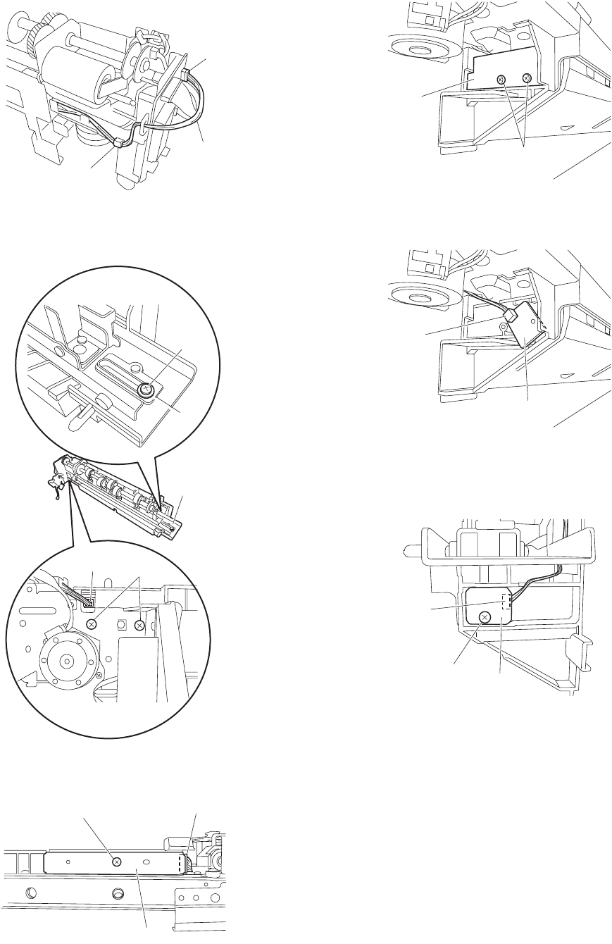
- (3)Removing the LED PCB 53
- [6] MAINTENANCE 54
- [7] MACHINE OPERATION 55
- The displayed menu will vary 56
- 12345678 57
- (Input display) 58
- (Execution display) 58
- [9] TROUBLE SHOOTING 59
- 3. Troubleshooting 60
- (6) F1-10, Slide Motor Fault 61
- (8) F1-15, Shift Motor Fault 62
- (9) F1-15, Shift Motor Fault 62
- (10) F1-15, Shift Motor Fault 62
- B. Puncher unit, option 63
- [10] SIMULATIONS 65
- [11] ELECTRICAL SECTION 67
- 2. Wiring diagram (AR-F14) 68
- Finisher controller PCB 69
- Stapler unit 69
- To puncher unit (option) 69
- To Interface transport unit 69
- 3. Wiring diagram (AR-PN1) 70
- Controller PCB 71
- CAUTION FOR BATTERY DISPOSAL 73
- COPYRIGHT 74
- 2004 BY SHARP CORPORATION 74
Související produkty a manuály pro Kopírky Sharp AR-F14
 (12 stránky)
(82 stránky)
(44 stránky)
(107 stránky)
(36 stránky)
(9 stránky)
(170 stránky)
(2 stránky)
(5 stránky)
(12 stránky)
(82 stránky)
(44 stránky)
(107 stránky)
(36 stránky)
(9 stránky)
(170 stránky)
(2 stránky)
(5 stránky)
 (88 stránky)
(34 stránky)
(1 stránky)
(181 stránky)
(12 stránky)
(5 stránky)
(1 stránky)
(13 stránky)
(9 stránky)
(58 stránky)
(88 stránky)
(34 stránky)
(1 stránky)
(181 stránky)
(12 stránky)
(5 stránky)
(1 stránky)
(13 stránky)
(9 stránky)
(58 stránky)
© 2020, manymanuals.cz. Všechna práva vyhrazena. | 0.040 s |
 Manymanuals.com
 Manymanuals.de
 Manymanuals.fr
 Manymanuals.it
 Manymanuals.pl
 Manymanuals.cz
 Manymanuals.es
 Manymanuals-pt.com
Komentáře k této Příručce