Sharp Printer AL-840 Uživatelský manuál
Procházejte online nebo si stáhněte Uživatelský manuál pro Monokuláry Sharp Printer AL-840. Sharp Printer AL-840 User's Manual Uživatelská příručka
- Strana / 31
- Tabulka s obsahem
- KNIHY

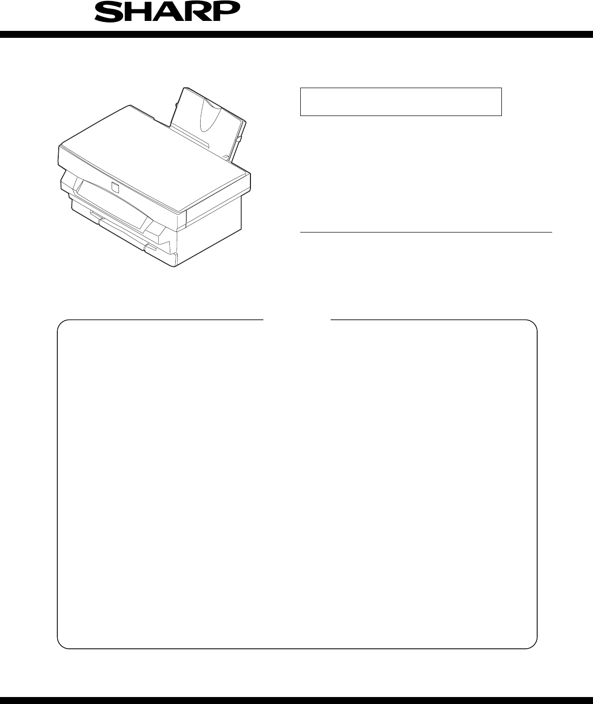
- SERVICE MANUAL 1
- AL-800/840 1
- [1] OPERATING PRINCIPLE 2
- Scanner (reading) section 3
- Fusing/paper exit section 3
- Scanner (writing) section 3
- Paper feed section 3
- Image process section 3
- 2. Outline of operations 4
- DATA FLOW DIAGRAM 5
- (1) Outline 6
- Paper feed roller 10
- Separate sheet 10
- Paper feed clutch lever 10
- Clutch R sleeve 10
- (2) Major parts 11
- (3) Operation 12
- C. Scanner (writing) section 13
- (4) Operation 14
- D. Image process section 15
- (3) Major parts 17
- (4) System diagram 20
- (5) Operation 20
- <2> Developing unit 21
- <5> High voltage unit 21
- Main charger brush 22
- Residual toner 22
- Aluminum layer 22
- (Drum base) 22
- OPC drum 22
- Aluminum surface 23
- Transfer roller 23
- Toner attraction 25
- E. Fusing/paper exit section 26
- MCU(PCU) PWB POWER SUPPLY PWB 27
- F. Drive section 28
- G. Electrical section 29
- MCU PWB BLOCK DIAGRAM 30
- COPYRIGHT 31
- 1998 BY SHARP CORPORATION 31
Shrnutí obsahu
SERVICE MANUALCODE: 00ZAL840//B1E BASIC MANUAL DIGITAL COPIERMODEL AL-800/840SHARP CORPORATIONThis document has been published to be usedfor after sal
The paper feed roller is of circular form, and double paper feed isprevented by the separate sheet.The paper feed clutch lever is provided to prevent
(2) Major partsNo.PartsNoteCode Signal name Name Type Function/operation Active condition1 Scanner lampcontrol PWBDrives the scanner lamp.Maintains th
(3) Operationa. Wiring diagram* Copy lampA cathode ray tube (Xenon lamp) is used as the light source forreading images.To maintain the lamp light quan
* CCD unitImages (light) is converted into an electrical signal (analog signal) bythe CCD.The image signal read by the CCD is converted into a digital
No.PartsNoteCode Signal name Name Type Function/operation Active condition1 SYNC SYNC IN Laser beam sensor Bin diode Detects the laser beam position.B
The scanning mirror is a 6-surface mirror. Six lines are printed for onerotation of the scanning motor. Laser beams reflected by the scan-ning mirror
(2) Image forming process diagramThe operation of this section are composed of the six processes:charging, exposure, development, transfer, separation
(3) Major partsa. Photoconductor sectionNo.PartsNoteName Type Function/operation1 OPC drum OPC Forms latent electrostatic images.2 OPC drum earth elec
b. Development sectionNo.PartsNoteName Type Function/operation1 Developing roller Attaches toner to the latent electrostaticimages on the OPC drum to
c. Transfer/separation sectionNo.PartsNoteName Function/operation1 Transfer roller Transfers toner images on the OPC drum onto the paper.2 Transfer ro
[1] OPERATING PRINCIPLE1. Block diagramCCDCPUASICMEMORYMEMORYICU PWBASICHOST(PC)KEYAC POWERControl signal, detection signal, drive signal, control dat
(4) System diagram(5) Operationa. Wiring diagramDC-200VDC-310VDC+500VDC-850VAC600V(P-P)DC +3.5KVAC600V(P-P)DC –850VDC +200VDC –310V–310V/+200Vselectio
b. Major parts functions and operations1 Developingroller5 Toner seal 9 Dischargebrush2 Doctor 6 Transfercharger roller10 Main chargerbrush3 Toner sti
c. Actual image forming processStep 1 (Cleaning, charging): Residual toner on the OPC drum isstirred and negative charges are dis-tributed evenly on t
Step 3 (Development): Toner is attached to the latent electrostaticimages formed on the OPC drum.Toner enters between the developing roller and the do
The positive charges are attracted to the OPC drum which is nega-tively charged, and put on the paper transported between the transferroller and the O
d. OPC drum surface potential<1> OPC drum surface potential shift in printing<2> OPC drum surface potential and developing biasvoltage dur
E. Fusing/paper exit section(1) OutlineToner attracted to the paper in the transfer section is fused by heatand pressure of the heat roller. The heat
(3) Operationa. Wiring diagramb. OperationThe heater lamp ON/OFF is controlled by the detection signal (volt-age value) from the thermistor to maintai
F. Drive section(1) OutlineThe main motor drives the paper feed section, the transport section,the image process section, and the fusing section . The
G. Electrical section(1) Block diagrama. Major sections operations and functionsMCU (PCU) PWBThe CPU controls the engine, and the ASIC performs image
Scanner (read) section In this section, the copy lamp (cathode ray tube, Xenon lamp)radiates light onto a document, and the reflected light is detecte
ICU PWBPrint data from the host (PC) are developed by the ASIC and the linememory (DRAM) to converted into full dot image data, which are thenoutputte
qCOPYRIGHT 1998 BY SHARP CORPORATIONAll rights reserved.Printed in Japan.No part of this publication may be reproduced,stored in a retrieval system,
2. Outline of operationsA. Paper path and imagingPaper is fed, transported, and discharged through the path indicatedwith the arrow in the figure belo
(2) Printer modeP1) Print data (compressed data) are sent from the host. (Imagedata (Data 1 – 8)P2) Print data are developed by the ASIC and the line
3. Operations of each sectionA. Paper feed, paper transport section(1) OutlineThe paper feed tray contains about 200 (250) sheets of paper.The paper i
No.PartsNoteCode Signal name Name Type Function/operation Active condition1 PE SENSOR PEMP IN Paper emptydetectorPhototransmissionsensorDetects paper
(3) Operationa. Block diagramb. Operation* The main motor is a 4-phase stepping motor of 2-phase excite-ment bipolar system, which serves as the drive
(Paper release operation)The lock lever arm is always pressed onto the paper release lever bythe spring. When the paper release lever is pulled towar
© 2020, manymanuals.cz. Všechna práva vyhrazena. | 0.025 s |
 Manymanuals.com
 Manymanuals.de
 Manymanuals.fr
 Manymanuals.it
 Manymanuals.pl
 Manymanuals.cz
 Manymanuals.es
 Manymanuals-pt.com
Komentáře k této Příručce