Sharp MX-M453U Instalační manuál
Procházejte online nebo si stáhněte Instalační manuál pro Kopírky Sharp MX-M453U. Sharp MX-M453U Installation manual Uživatelská příručka
- Strana / 117
- Tabulka s obsahem
- KNIHY
- INSTALLATION MANUAL 1
- CONTENTS 2
- CONFIGURATION 3
- 2. Main unit configuration 4
- 3. Combination of options 4
- [1] MX-M283N/M363N/M363U/ 6
- M453N/M453U/M503N/M503U/ 6
- M282N/M362N/M452N/M502N 6
- (2) Dust 7
- (3) Direct rays of the sun 7
- (4) Gases and chemicals 7
- (5) Vibration 7
- 2. Transit and delivery 8
- 3. Unpacking 8
- 4. Installation 9
- B. Developer supply 10
- Inlet cover 10
- (1) Simulation setup 12
- (2) Tray size setup 12
- SHARP GRAY CHART 13
- (1) General 14
- [2] MX-DEX8/DEX9 15
- D. Release the lock 18
- E. Connector connection 18
- [3] MX-LCX1 20
- D. Connector connection 23
- E. Paper size switch 23
- F side R side 24
- G. Size setting 27
- H. Off-center adjustment 27
- [4] MX-FNX9 29
- 2. Installation 30
- D. Connector Installation 32
- [5] MX-PNX1 34
- [6] MX-RBX3 38
- [7] MX-FN10 41
- Guide pin 43
- Connection hole 43
- F. Connector connection 44
- Label attachment 45
- Corner R end fitting 45
- [8] MX-PNX5A/B/C/D 46
- Label attachment reference 48
- [9] MX-FN11 50
- 2. Installation 52
- D. Attaching the mylar 53
- F. Attaching the cushion 54
- H. Adjustment 54
- I. Connection of the finisher 58
- [10] MX-PNX6A/B/C/D 60
- E. Adjustment 63
- F. Install to main unit 63
- [11] MX-TRX2 66
- D. Tray setting 67
- [12] MX-FXX2 68
- D. Attach the FAX memory 69
- J. Clear the image memory 71
- [13] AR-SU1 72
- [14] MX-PB10 75
- [15] MX-PB11 76
- C. Pull out the control PWB 77
- D. HDD installation 77
- I. Deletion of backup data 78
- [16] MX-FWX1 79
- Identification marking 80
- $&5(%227 83
- - 83
- [18] MX-PKX1 84
- [19] MX-PUX1 85
- [20] MX-SMX3 86
- MX-M503N MX-SMX3 20 – 3 88
- [21] AR-PF1 89
- Service Manual 91
- 1. Unpacking 91
- FAX IMG EXT 92
- PCL/BARCODE 92
- PS KANJI 92
- [23] MX-KBX2 93
- C. Install the base unit 94
- G. Check the keyboard input 96
- H. Language setting 96
- Keyboard Select 97
- CClloocckk AAddjjuusstt 97
- SSyysstteemm SSeettttiinnggss 97
- [24] MX-AMX1 98
- [25] MX-AMX2 99
- [26] MX-AMX3 100
- [27] Dehumidifying heater 101
- DH POWER 102
- Reference line 103
- Reference 103
- 230V Series 104
- 120V Series 104
- [28] MX-RP11 107
- MX-M503N MX-RP11 28 – 3 109
- : '10/Jun/18 109
- MX-M503N MX-RP11 28 – 4 110
- MX-M503N MX-RP11 28 – 5 111
- (Front side) 112
- (Back side) 112
- (RSPF mode) 114
- LEAD-FREE SOLDER 115
- CAUTION FOR BATTERY DISPOSAL 116
- Trademark acknowledgements 117
Shrnutí obsahu
INSTALLATION MANUALParts marked with " " are important for maintaining the safety of the set. Be sure to replace these parts withspecified o
MX-M503N MX-M283N/M363N/M363U/M453N/M453U/M503N/M503U/M282N/M362N/M452N/M502N 1 – 5: '10/Jun/181(3) Removal of the fusing heat roller protector
MX-M503N MX-AMX3 26 – 1MX-M503NService Manual [26] MX-AMX3* This option requires installation of a HDD, and cannot beused with the models having no
MX-M503N Dehumidifying heater 27 – 1MX-M503NService Manual [27] Dehumidifying heater1. Parts included2. Installation<Note before installation&g
MX-M503N Dehumidifying heater 27 – 22) Cut the switch part of the left rear lower cabinet.NOTE: Be careful not to damage the cabinet.3) Attach the l
MX-M503N Dehumidifying heater 27 – 3C. Installation of the heater kit(1) Assembling of the heater unit1) Attach the heater (package part No. 6) to t
MX-M503N Dehumidifying heater 27 – 44) Attach the core (This procedure only applies to the 230Vseries).Attach the AC-cable connection plate (only fo
MX-M503N Dehumidifying heater 27 – 5(2) Removal of the table glass, the paper exit cover1) Remove the screw, and remove the SPF glass and the glassh
MX-M503N Dehumidifying heater 27 – 66) Move the lamp unit by hand and check that it move smoothly inall movable area.NOTE: Check that there is no in
MX-M503N MX-RP11 28 – 1MX-M503NService Manual [28] MX-RP111. UnpackingA. Removal of the RSPFB. Check the packed items1) Check that all the items are
MX-M503N MX-RP11 28 – 22) Cut the screw hole in the cabinet, and install the SPF stepscrew R (a) (package part No. 3) and the step screw R (b)(packa
MX-M503N MX-RP11 28 – 3C. RSPF parallelism adjustment1) Make an RSPF parallelism adjustment sheet.Cut copy paper in the longitudinal direction.2) Pe
MX-M503N MX-M283N/M363N/M363U/M453N/M453U/M503N/M503U/M282N/M362N/M452N/M502N 1 – 6: '10/Jun/181C. Toner density reference control level settin
MX-M503N MX-RP11 28 – 4Is there aresistance in thesection B?YesNoIncrease theclearance inthe section Funtil there is aresistance inthe section B.How
MX-M503N MX-RP11 28 – 5YesYesNoNoEnd of theadjustmentThe bosses in section Aand B are excessivelypressed. (The rightside is separating.)Adjust hinge
MX-M503N MX-RP11 28 – 6D. RSPF skew adjustment (Front surface mode)This adjustment is needed in the following situations:* The RSPF section has been
MX-M503N MX-RP11 28 – 75) Close the RSPF unit, and loosen the hex nut of the RSPFdiagonal adjustment screw section.Turn the hex wrench of the RSPF d
MX-M503N MX-RP11 28 – 8: '10/Jun/181F. Copy image off-center, image lead edge position, sub scanning direction image magnification ratio automa
No part of this publication may be reproduced,stored in a retrieval system, or transmitted inany form or by any means, electronic, mechanical,photoco
(Danish) ADVARSEL !Lithiumbatteri – Eksplosionsfare ved fejlagtig håndtering.Udskiftning må kun ske med batteriaf samme fabrikat og type.Levér det br
SHARP CORPORATIONBusiness Solutions GroupCS Promotion CenterYamatokoriyama, Nara 639-1186,Japan2010 June Produced in Japan for electronic Distributio
MX-M503N MX-M283N/M363N/M363U/M453N/M453U/M503N/M503U/M282N/M362N/M452N/M502N 1 – 73) Install the paper holding plate unit.* If the MX-FNX9 (Inner F
MX-M503N MX-M283N/M363N/M363U/M453N/M453U/M503N/M503U/M282N/M362N/M452N/M502N 1 – 82) Adjust the guide plates A and B by squeezing their lock levers
MX-M503N MX-M283N/M363N/M363U/M453N/M453U/M503N/M503U/M282N/M362N/M452N/M502N 1 – 9J. Function and operation checkCheck that the following operation
MX-M503N MX-DEX8/DEX9 2 – 1MX-M503NService Manual [2] MX-DEX8/DEX91. UnpackingA. Removal of the desk unitB. Removal of the fixing material and pack
MX-M503N MX-DEX8/DEX9 2 – 2B. Installation of the adjuster1) Install the right adjuster (package part No. 1) to the desk unit.2) Turn each adjuster
MX-M503N MX-DEX8/DEX9 2 – 35) Lift the connection plates on the right and left of the main unitfront side, and fix them with the fixing screws (pack
MX-M503N MX-DEX8/DEX9 2 – 4D. Release the lock1) Pull out each tray.2) Turn and remove the fixing material, and remove the cautionsheet.3) Attach th
MX-M503N MX-DEX8/DEX9 2 – 5F. Turn on the power of the main unit1) Insert the power plug of the main unit into the power outlet.2) Open the front ca
CONTENTS: '10/Jun/181CONFIGURATION1. Main unit and option. . . . . . . . . . . . . . . . . . . . . . .i2. Main unit configuration. . . . . . . .
MX-M503N MX-LCX1 3 – 1MX-M503NService Manual [3] MX-LCX11. UnpackingA. Removal of the large capacity tray unitB. Removal of the fixing material and
MX-M503N MX-LCX1 3 – 22) Open the front cabinet.Turn OFF the power switch in the front cabinet of the main unit.3) Disconnect the power plug of the
MX-M503N MX-LCX1 3 – 37) Insert the temporarily fixed screw B into the key hole in theconnection unit (package part No. 2), and temporarily fix thec
MX-M503N MX-LCX1 3 – 45) In the case of a shift to the right, press the front upper sectionand fit the height adjustment check rib so that it is in
MX-M503N MX-LCX1 3 – 5a. Side plate size switch1) Remove four fixing screws (blue screws) which are fixing theupper and the lower sections of the si
MX-M503N MX-LCX1 3 – 63) Slightly push the tray, restore the stopper to the original posi-tion, and fix the fixing screw.At that time, check to insu
MX-M503N MX-LCX1 3 – 7b. Auxiliary guide size switch* Since the auxiliary guide setting is not required, fix the auxiliaryguide to either of A4 or L
MX-M503N MX-LCX1 3 – 82) Open the front cabinet.Turn ON the power switch in the front cabinet of the main unit. 3) Turn ON the power switch on the o
MX-M503N MX-LCX1 3 – 92) Loosen the stopper fixing screw (1 pc) on the right lower sideof the tray so that the stopper does not function.3) Pull out
MX-M503N MX-FNX9 4 – 1MX-M503NService Manual [4] MX-FNX91. UnpackingA. Removal of the inner finisher* When removing the inner finisher, lift it as
MX-M503N CONFIGURATION - i: '10/Jun/181MX-M503NService Manual CONFIGURATION1. Main unit and option1Paper exit systemPaper feed systemMX-SCX11210
MX-M503N MX-FNX9 4 – 2: '10/Jun/1812. Installation<Note before installation>* Before starting installation, check to insure that the dat
MX-M503N MX-FNX9 4 – 35) Remove the paper exit full detection actuator.6) Engage the projection on the main unit frame with the hole inthe finisher
MX-M503N MX-FNX9 4 – 413) Install the front open/close cover (package part No. 4) to thefront rail stay rotating shaft, and fix it with the resin cl
MX-M503N MX-FNX9 4 – 5E. Staple position label attachment1) Attach the label to the position indicated in the figure.[For scanner] (package part No.
MX-M503N MX-PNX1 5 – 1MX-M503NService Manual [5] MX-PNX11. UnpackingA. Removal of the punch unitB. Removal of the fixing tape1) Remove the fixing t
MX-M503N MX-PNX1 5 – 2B. Installation of the punch unit1) Open the front cabinet.2) Open the front cover and slide the inner finisher to the left.3)
MX-M503N MX-PNX1 5 – 39) Make positioning with the dove (A) and fix the punch unit withthe screw which was fixing the dummy punch unit.10) Cut the l
MX-M503N MX-PNX1 5 – 4C. Punch position label attachment1) Attach the label to the position indicated in the figure.[For scanner] (Part No. 13 in th
MX-M503N MX-RBX3 6 – 1MX-M503NService Manual [6] MX-RBX31. UnpackingA. Removal of the interface pass unitB. Removal of the fixing tape1) Remove the
MX-M503N MX-RBX3 6 – 2: '10/Jun/181B. Removal of the paper holding plate unit 1) Disengage the pawl, and remove the paper holding plate andthe
MX-M503N CONFIGURATION - ii: '10/Jun/1812. Main unit configurationSTD: Standard provision. OPT: Option. OPT*1: Product key target.3. Combination
MX-M503N MX-RBX3 6 – 36) Insert the rib of the interface left cabinet (package part No. 2)into the slit on the lower surface of the scanner left cab
MX-M503N MX-FN10 7 – 1MX-M503NService Manual [7] MX-FN101. UnpackingA. Removal of the saddle finisher* For removal of the saddle stitch finisher, m
MX-M503N MX-FN10 7 – 2B. Removal of the fixing tape and protection material1) Remove the fixing tape and protection material.C. Check the packed ite
MX-M503N MX-FN10 7 – 32) Fix the paper holding A with fixing screws A (package part No.6).3) Installation of tee saddle tray and paper holding B.C.
MX-M503N MX-FN10 7 – 4(2) When the guide pin is fit with the connection hole in the finisher:1) Insert the finisher into the main unit. Check to ins
MX-M503N MX-FN10 7 – 52) Connect the finisher connector with the connector of the mainunit, and tighten the screw.G. Staple position label attachmen
MX-M503N MX-PNX5A/B/C/D 8 – 1MX-M503NService Manual [8] MX-PNX5A/B/C/D1. UnpackingA. Removal of the punch unitB. Check the packed items1) Check that
MX-M503N MX-PNX5A/B/C/D 8 – 22) Remove the screw, and remove the rear cover.3) Remove the screw, and remove the front lower cover.4) Open the front
MX-M503N MX-PNX5A/B/C/D 8 – 38) Fix the front inner cover with screws, and close the frontcover. 9) Fix the front lower cover with a screw.10) Fix t
MX-M503N MX-PNX5A/B/C/D 8 – 4[For DSPF/RSPF]E. Turn on the power of the main unit1) Connect the connector.2) Insert the power plug of the main unit
MX-M503N CONFIGURATION - iiiSTD: Standard provision. {: Installable. —: Cannot be connected.*1: No support for some destinations. *2: Standard for No
MX-M503N MX-FN11 9 – 1MX-M503NService Manual [9] MX-FN111. UnpackingA. Removal of the finisher* For removal of the finisher, manpower of two persons
MX-M503N MX-FN11 9 – 2B. Removal of the protection material1) Remove the fixing tapes and protection material.2) Open the front upper door, and remo
MX-M503N MX-FN11 9 – 32. Installation<Note before installation>* Installing the MX-FN11 requires that the option desk (MX-DEX8/DEX9) and junct
MX-M503N MX-FN11 9 – 44) Remove the reverse tray.5) Remove the screws, and remove the interface left cabinet.6) Remove the screws, and remove the pa
MX-M503N MX-FN11 9 – 5F. Attaching the cushion1) Attach the cushion (S) (package part No.14), the cushion (M)(package part No.15) and the cushion (L
MX-M503N MX-FN11 9 – 62) Remove the screw, slide to the left the front lower cover, andremove it.3) Open the front upper door, and remove the screw.
MX-M503N MX-FN11 9 – 79) Loosen both of the caster fixing screws of the front side andrear side.10) Remove the screw, and remove the spanner install
MX-M503N MX-FN11 9 – 813) Tighten the caster fixing screws so that the indicator scale isfit.14) Install the rear lower cover with the fixing screws
MX-M503N MX-FN11 9 – 919) Attach the front lower cover with the fixing screw.I. Connection of the finisher1) Engage the finisher to the main unit.2)
MX-M503N MX-FN11 9 – 10J. Connection of connector to the main unit1) Connect two connectors of the finisher to the main unit, andtighten the screws.
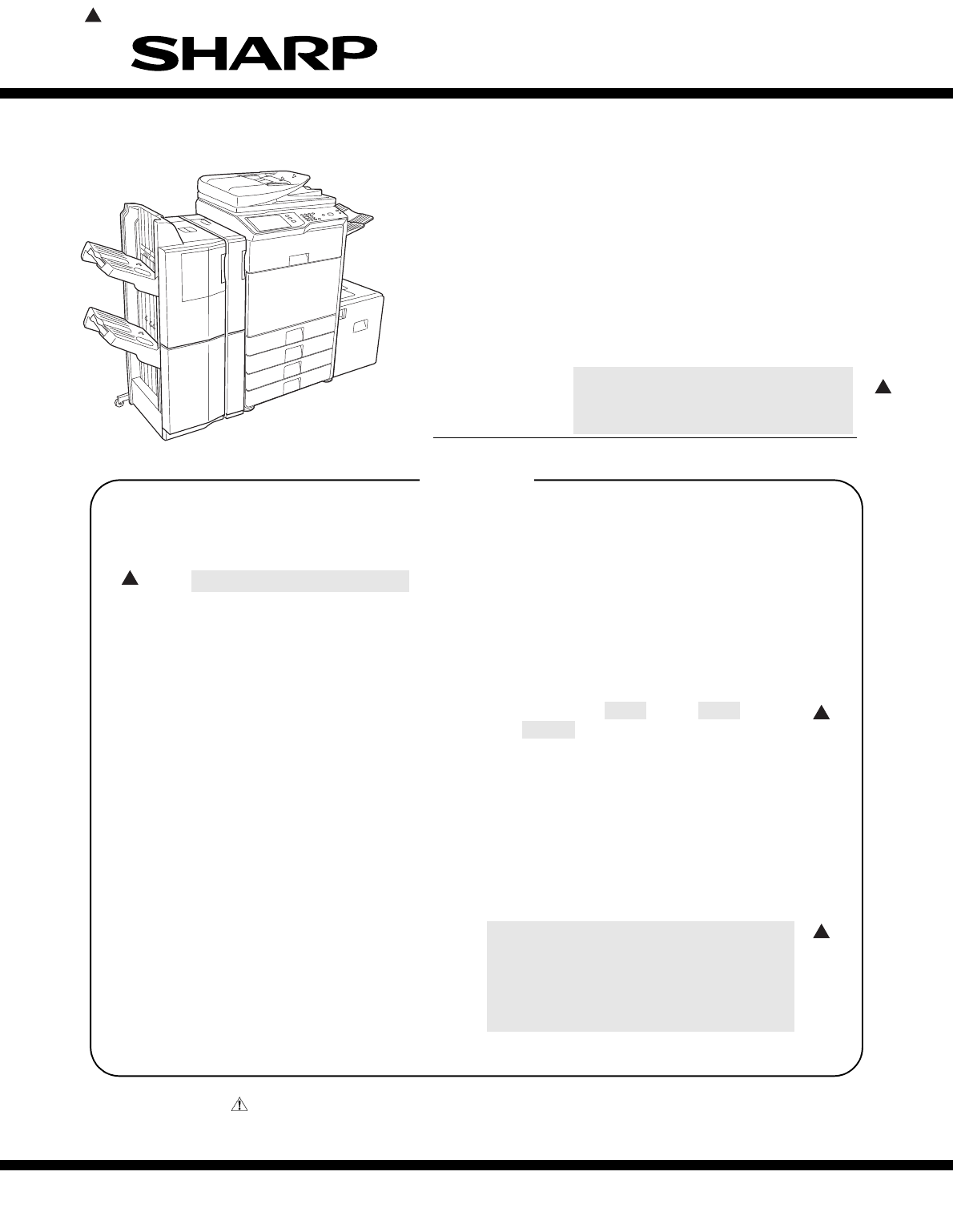
MX-M503N MX-M283N/M363N/M363U/M453N/M453U/M503N/M503U/M282N/M362N/M452N/M502N 1 – 1: '10/Jun/181MX-M503NService Manual [1] MX-M283N/M363N/M363U
MX-M503N MX-PNX6A/B/C/D 10 – 1MX-M503NService Manual [10] MX-PNX6A/B/C/D1. UnpackingA. Pulling out of the punch unit1) Pull out the punch unit.B. Re
MX-M503N MX-PNX6A/B/C/D 10 – 2C. Check the packed items1) Check that all the items are included in the package.2. Installation<Note before instal
MX-M503N MX-PNX6A/B/C/D 10 – 36) Open the front door of punch unit.7) Engage the pawls of the rear side of front cover (Package partNo. 5), attach t
MX-M503N MX-PNX6A/B/C/D 10 – 42) Open the front door of punch unit.3) Check that the center of the screw hole of the punch unit is inthe range of sp
MX-M503N MX-PNX6A/B/C/D 10 – 54) Close the front door of punch unit.5) Install the fixing screw (Package part No. 4 of MX-FN11) onrear side.6) Insta
MX-M503N MX-PNX6A/B/C/D 10 – 6[For DSPF/RSPF] (Package part No. 12 of the MX-FN11)I. Turn ON the main power switch of the main unit1) Connect the po
MX-M503N MX-TRX2 11 – 1MX-M503NService Manual [11] MX-TRX21. UnpackingA. Removal of the exit tray unitB. Check the packed items1) Check that all the
MX-M503N MX-TRX2 11 – 24) Connect the connector, and install the exit roller unit (packagepart No. 1). Use the screw which was removed in step 3) an
MX-M503N MX-FXX2 12 – 1MX-M503NService Manual [12] MX-FXX21. UnpackingA. Parts included2. Installation<Note before installation>• Start inst
MX-M503N MX-FXX2 12 – 23) Remove the two screws from the control PWB unit.4) Pull out the control PWB unit.D. Attach the FAX memory.E. Attach the in
MX-M503N MX-M283N/M363N/M363U/M453N/M453U/M503N/M503U/M282N/M362N/M452N/M502N 1 – 2(2) DustIf dust enters the machine, it may cause dirty copy and a
MX-M503N MX-FXX2 12 – 3G. Turn on the main power switch of the main unit.1) Insert the power plug of the main unit to the outlet.2) Turn on the main
MX-M503N MX-FXX2 12 – 4J. Clear the image memory.1) Enter the SIM 66-10 mode.2) Press [EXECUTE] key and then [YES] key. (The FAX imagememory is clea
MX-M503N AR-SU1 13 – 1MX-M503NService Manual [13] AR-SU11. UnpackingA. Remove the stamp unitB. Check the parts in the package1) Check to confirm th
MX-M503N AR-SU1 13 – 22) Remove the sensor cover. Remove the stamp case, andremove the earth cord.3) Attach the stamp unit (package part No. 1) to t
MX-M503N AR-SU1 13 – 3C. Turn on the power of the main unit1) Insert the power plug into the power outlet.2) Open the front cabinet of the machine,
MX-M503N MX-PB10 14 – 1MX-M503NService Manual [14] MX-PB101. UnpackingA. Parts included2. InstallationA. Preparation for enabling the MX-PB101) To e
MX-M503N MX-PB11 15 – 1MX-M503NService Manual [15] MX-PB111. UnpackingA. Parts included2. InstallationA. Preliminary arrangementsNOTE: When this opt
MX-M503N MX-PB11 15 – 2C. Pull out the control PWB• If cables are connected to the control PWB unit, remove allcables.1) Push the location indicated
MX-M503N MX-PB11 15 – 34) Push the control PWB unit into the main unit.5) Secure the unit with the two screws.6) Fit the interface cable into the ri
MX-M503N MX-FWX1 16 – 1MX-M503NService Manual [16] MX-FWX1* This option requires installation of a HDD, and cannot beused with the models having no
MX-M503N MX-M283N/M363N/M363U/M453N/M453U/M503N/M503U/M282N/M362N/M452N/M502N 1 – 3: '10/Jun/181G. Note for handling the drum unit, the transfe
MX-M503N MX-EBX3 17 – 1: '10/Jun/181MX-M503NService Manual [17] MX-EBX3* This option cannot be installed to the U model.1. UnpackingThe MX-EBX3
MX-M503N MX-EBX3 17 – 22. InstallationA. Turn off the power of the main unit1) Turn the power switch located on the operation panel to the"OFF&
MX-M503N MX-EBX3 17 – 33) Remove the S tight screw (section A) of the controller PWB.Use the removed S tight screw and the S tight screw providedin
MX-M503N MX-EBX3 17 – 42) Open the front cabinet. Turn ON the power switch in the frontcabinet of the main unit.3) Turn ON the power switch on the o
MX-M503N MX-PKX1 18 – 1 MX-M503NService Manual [18] MX-PKX11. UnpackingA. Parts includedNOTE:• N modelTo set up the PS driver, do not use the CD-ROM
MX-M503N MX-PUX1 19 – 1MX-M503NService Manual [19] MX-PUX11. UnpackingA. Check the packed items2. Installation<Note before installation>To ena
MX-M503N MX-SMX3 20 – 1MX-M503NService Manual [20] MX-SMX31. UnpackingA. Parts included2. InstallationA. Turn off the power switches of the main u
MX-M503N MX-SMX3 20 – 2NOTE: Avoid diagonal insertion of the expansion memory board for the slot.NOTE: Do not push one end of the expansion memory b
MX-M503N MX-SMX3 20 – 32) Turn on the main power switch.3) Turn on the power switch located on the operation panel.ON
MX-M503N AR-PF1 21 – 1MX-M503NService Manual [21] AR-PF11. UnpackingA. Parts included2. InstallationA. Turn off the power switches of the main unit.
MX-M503N MX-M283N/M363N/M363U/M453N/M453U/M503N/M503U/M282N/M362N/M452N/M502N 1 – 4: '10/Jun/181• MX-M282N/M362N/M452N/M502NC. Check the parts
MX-M503N AR-PF1 21 – 2D. Reattach the control PWB and the right cabinet rear.• If the fax box unit is installed, carry out steps 1), 2), and 3)addit
MX-FR14U/FR14/FR15U/FR15/FR24U 22 – 1: '10/Jun/181Service Manual [22] MX-FR14U/FR14/FR15U/FR15/FR24U* MX-FR14U/FR14For model MX-M283N/M363N/M4
MX-FR14U/FR14/FR15U/FR15/FR24U 22 – 2C. Mount the data security kit ROMs to the control PWB unit.Remove the ROMs (PROG1 and PROG2) from the control
MX-M503N MX-KBX2 23 – 1MX-M503NService Manual [23] MX-KBX2* This option cannot be installed to the following models.MX-M363U/M453U/M503UMX-M282N/M36
MX-M503N MX-KBX2 23 – 22) Disconnect the connector of the scan mother harness, andremove the screws.3) Attach the USB hub PWB unit (part No.3 in the
MX-M503N MX-KBX2 23 – 34) Remove the screws and disconnect two connectors. Place theoperation panel upside down on the protection sheet. *1: Don&apo
MX-M503N MX-KBX2 23 – 45) Slide and attach the operation base plate C (part No.2 in thepackage) to the operation base plate unit.6) Install the oper
MX-M503N MX-KBX2 23 – 53) Touch [Keyboard Select].4) Select your desired language and touch [OK].The keyboard layouts that can be selected are shown
MX-M503N MX-AMX1 24 – 1MX-M503NService Manual [24] MX-AMX1* This option requires installation of a HDD, and cannot beused with the models having no
MX-M503N MX-AMX2 25 – 1MX-M503NService Manual [25] MX-AMX2* This option requires installation of a HDD, and cannot beused with the models having no
Související produkty a manuály pro Kopírky Sharp MX-M453U
 (12 stránky)
(16 stránky)
(8 stránky)
(8 stránky)
(4 stránky)
(12 stránky)
(16 stránky)
(8 stránky)
(8 stránky)
(4 stránky)


 (20 stránky)
(57 stránky)
(72 stránky)
(69 stránky)
(12 stránky)
(91 stránky)
(12 stránky)
(12 stránky)
(12 stránky)
(81 stránky)
(84 stránky)
(118 stránky)
(48 stránky)
(16 stránky)
(72 stránky)
(20 stránky)
(57 stránky)
(72 stránky)
(69 stránky)
(12 stránky)
(91 stránky)
(12 stránky)
(12 stránky)
(12 stránky)
(81 stránky)
(84 stránky)
(118 stránky)
(48 stránky)
(16 stránky)
(72 stránky)
© 2020, manymanuals.cz. Všechna práva vyhrazena. | 0.041 s |
 Manymanuals.com
 Manymanuals.de
 Manymanuals.fr
 Manymanuals.it
 Manymanuals.pl
 Manymanuals.cz
 Manymanuals.es
 Manymanuals-pt.com
Komentáře k této Příručce