Sharp CD-BA1700H Servisní příručka
Procházejte online nebo si stáhněte Servisní příručka pro Kazetové přehrávače Sharp CD-BA1700H. Sharp CD-BA1700H Service manual Uživatelská příručka
- Strana / 64
- Tabulka s obsahem
- KNIHY
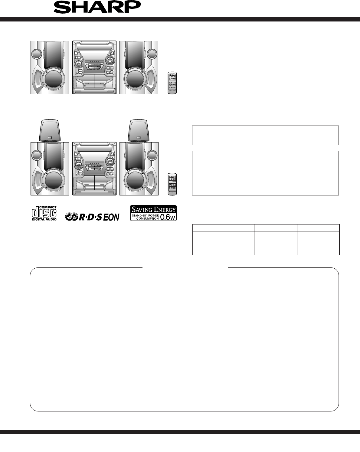
- CD-BA160H 1
- CD-BA1700H 1
- SAFETY PRECAUTION FOR 2
- SERVICE MANUAL 2
- SPECIFICATIONS 3
- NAMES OF PARTS 4
- Front speaker 5
- Remote control 5
- OPERATION MANUAL 6
- Connections 7
- ● CD pickup cleaning 8
- Recording from CDs 8
- DISASSEMBLY 9
- CD-BA160H/1700H 10
- TAPE MECHANISM SECTION 12
- CD MECHANISM SECTION 13
- ADJUSTMENT 14
- C D T E S T 15
- ASPM, summary operation 16
- 4, f5 (same PTY) 17
- 1, f2, f3 (same PTY) 17
- NOTES ON SCHEMATIC DIAGRAM 20
- DISPLAY 36
- WAVEFORMS OF CD CIRCUIT 39
- TROUBLE SHOOTING 40
- Vp-p=1.0V~1.3V 41
- 0.5mV/div,0.5µsec/div 41
- LC78641E 44
- M63001FP 48
- 123456789101112 49
- 1G 2G 3G 4G 5G 6G 7G 8G 50
- OTHER CIRCUITRY PARTS 55
- MECHANISM 60
- Front Speaker 61
- GBOXS0041AWM1 62
- FRONT SIDE OF 63
- SPEAKERS 63
- ALL RIGHTS RESERVED 64
Shrnutí obsahu
– 1 –CD-BA160H/1700HNo. S4024CDBA160H CONTENTSPageSAFETY PRECAUTION FOR SERVICE MANUAL ...
CD-BA160H/1700H– 10 –Figure 10-2Figure 10-3Figure 10-4Figure 10-5Figure 10-6Figure 10-1Note 1:How to open the changer manually. (Fig. 10-3)1. In this
– 11 –CD-BA160H/1700HCP-BA160H/1700H (Front Speaker)1 Woofer/ 1. Front Panel ... (A1) x1 11-1Sub Woofer 2. Screw ... (A2) x
CD-BA160H/1700H– 12 –REMOVING AND REINSTALLING THE MAIN PARTSTAPE MECHANISM SECTIONPerform steps 1 to 8 and 10 of the disassembly method toremove the
– 13 –CD-BA160H/1700HHow to remove the pickup (See Fig. 13-3)1. Remove the screws (B1) x 2 pcs., to remove the shaft (B2)x1pc.2. Remove the stop washe
CD-BA160H/1700H– 14 –• AM IF/RFSignal generator: 400 Hz, 30%, AM modulated*1. Input: Antenna, Output: TP302*2. Input: Antenna, Output: TP301TUNER SECT
– 15 –CD-BA160H/1700HAny one of test mode can be set by pressing several keys asfallows. <X-BASS> + <CD> + <POWER> TEST:CD operation
CD-BA160H/1700H– 16 –ASPM, summary operationYesYesComparing freg.same or not?Between current receivingfrequency and (already)previously memorizedfrequ
– 17 –CD-BA160H/1700H4. No adjust type (None adjusting circuit.)5. Added EON button.6. Need to change RDS logo due to the addition of EON feature.7. A
CD-BA160H/1700H– 18 –EON summary notice for reference1. EON-TI/PTY EON stand-by can be set, only when EON ind. lights up.While EON ind. goes out (NO E
– 19 –CD-BA160H/1700HRDS (Radio Data System) OPERATIONRDS is a broadcasting service which a growing number ofFM stations are now providing. It allows
CD-BA160H/1700H– 2 –SAFETY PRECAUTION FORSERVICE MANUALPrecaution to be taken when replacing and servicing theLaser Pickup.The AEL (Accessible Emissio
CD-BA160H/1700H– 20 –• The indicated voltage in each section is the one measuredby Digital Multimeter between such a section and the chas-sis with no
– 21 –CD-BA160H/1700H Figure 21 BLOCK DIAGRAM (1/3)CNP12 CNP11Q2+3.3V +5V CONT5CONT2CONT3CONT4CONT7CONT6SLDOSPDOFDOTDO+5V TO DISPLAY SECTIONCLAMP SWCD
CD-BA160H/1700H– 22 – Figure 22 BLOCK DIAGRAM (2/3)AM LOOPANTENNAXIN VDDDVSSDDOCLDICEXOUTVDDAVSSAINMPX FM AFCBALUN REC/PLACLCEDISYSTEMMUTE DOCLDIC
– 23 –CD-BA160H/1700H Figure 23 BLOCK DIAGRAM (3/3)+B2 +5V 5VEC/PLAYVLOAD +B3 RESET ICSYS. STOP RESET +B2 M901FAN MOTOR M +B3 +B3 +B3 +B3 VDD VDD V
CD-BA160H/1700H– 24 –Figure 24 SCHEMATIC DIAGRAM (1/10)ABCDEFGH123456• NOTES ON SCHEMATIC DIAGRAM can be found on page 20.GND L GND +5V R M_GND (CD_GN
– 25 –CD-BA160H/1700HFigure 25 SCHEMATIC DIAGRAM (2/10)78 9 10 11 121 1 A_10V TUN_SMDOCEVF1 -VP VF2 SP_RLYM_10V -15VGND SW_5V GND UN_SW_5VAC_RLY_CON
CD-BA160H/1700H– 26 –ABCDEFGH123456• NOTES ON SCHEMATIC DIAGRAM can be found on page 20.Figure 26 SCHEMATIC DIAGRAM (3/10)3 2 1 3 2 1 321A_10V M_10V
– 27 –CD-BA160H/1700HFigure 27 SCHEMATIC DIAGRAM (4/10)78 9 10 11 12-28V -28V -33V 4.4V 0.2V R1_OUTL1_OUT34455667788M2211112212345213C93122/50 8 OHMS
CD-BA160H/1700H– 28 –Figure 28 SCHEMATIC DIAGRAM (5/10)ABCDEFGH123456• NOTES ON SCHEMATIC DIAGRAM can be found on page 20. CONTIF FM/AM FM/AM AM
– 29 –CD-BA160H/1700HFigure 29 SCHEMATIC DIAGRAM (6/10)78 9 10 11 129 102423222120 19 1817161514 1311128 7 6 5 4 3 2 1 1 2 345678GND CEDODICLK GND A_1
– 3 –CD-BA160H/1700HFOR A COMPLETE DESCRIPTION OF THE OPERATION OF THIS UNIT, PLEASE REFERTO THE OPERATION MANUAL.Specifications for this model are su
CD-BA160H/1700H– 30 –Figure 30 SCHEMATIC DIAGRAM (7/10)ABCDEFGH123456• NOTES ON SCHEMATIC DIAGRAM can be found on page 20.-25.7V 3.3V -25.7V 3.3V -25.
– 31 –CD-BA160H/1700HFigure 31 SCHEMATIC DIAGRAM (8/10)78 9 10 11 12 5.9V 5.9V 0V 0V 0V 4.8V SPA_SIG SP_RLYM_GND SP_DETTUN SMDO5V BACK UPF CLK CEDI
CD-BA160H/1700H– 32 –ABCDEFGH123456• NOTES ON SCHEMATIC DIAGRAM can be found on page 20.Figure 32 SCHEMATIC DIAGRAM (9/10)• The numbers 1 to 13
– 33 –CD-BA160H/1700H78 9 10 11 12Figure 33 SCHEMATIC DIAGRAM (10/10)R1610KL610.82µHR87120C56330/6.3C640.47/6.3ZD61DZ3.9BSBR9410KR9510KCNP11C368.2PC35
CD-BA160H/1700H– 34 –Figure 34 WIRING SIDE OF P.W.BOARD (1/4)ABCDEFGH123456R142C138C150R139C134R140C144C131Q111C136C130C135C128C129C122IC101C139C118R1
– 35 –CD-BA160H/1700HFigure 35 WIRING SIDE OF P.W.BOARD (2/4)78 9 10 11 12L951JK951HEADPHONESR952R951C951C952CNP951FW9511234515HEADPHONESPWB-A3RDS PWB
CD-BA160H/1700H– 36 –Figure 36 WIRING SIDE OF P.W.BOARD (3/4)ABCDEFGH123456BI701 RDBKWHBKWHBKWHBKWHBKWHBKC621SW601ON/STAND-BYR696R700SW602CLOCKD617R72
– 37 –CD-BA160H/1700HFigure 37 WIRING SIDE OF P.W.BOARD (4/4)78 9 10 11 12• The numbers 1 to 13 are waveform numbers shown in page 39.CNS402FROM
CD-BA160H/1700H– 38 –VOLTAGE0V(0V)PIN NO. VOLTAGE 7 8 FE301 1 2 3 4 5 6 0V(0V)0V(0V)2.6V(0V)2V(1.1V)0V(0V)0V(0V)8.5V(0V)2.6V6 5 4 3 2 1 ICT21 242322
– 39 –CD-BA160H/1700HWAVEFORMS OF CD CIRCUITTFDOTDOStoppedCH1=500mVDC 10:1CH3=500mVDC 10:1500ms/div(500ms/div)NORM:20kS/s13=Record Length=Smoothin
CD-BA160H/1700H– 4 –NAMES OF PARTSCD-BA160H/1700HFront panel1. (CD) Disc Tray2. (TUNER) Programme Type/Traffic Information Search Button3. EON Button4
CD-BA160H/1700H– 40 –Parts code1. CD optical pickup Lens cleaner disc UDSKA0004AFZZTROUBLE SHOOTINGWhen the CD does not functionWhen the CD section do
– 41 –CD-BA160H/1700HIf the level is not normal, check around pins 27~29 on IC1.1. Is focus servo activated? (Waveform drawing 41-2) Pins 1~11 on IC1C
CD-BA160H/1700H– 42 –The tracking servo is not activated.Check the peripheral circuits at pins 18 and 19 on IC1, pin 23 onIC2, and CNS1A/B.If the wave
– 43 –CD-BA160H/1700HIs pin 35 (C2F) on IC2 "L"?YesNoThe HF waveform is normal and the time is displayednormally, but no sound is produced.
CD-BA160H/1700H– 44 –FUNCTION TABLE OF ICFigure 44 BLOCK DIAGRAM OF ICIC1 VHiLA9235M/-1: Servo Amp. (LA9235M)IC2 VHiLC78641E-1: Servo/Signal Control
– 45 –CD-BA160H/1700HIC2 VHiLC78641E-1: Servo/Signal Control (LC78641E) (1/2)1 PDO1 Output – For PULL Phase-comparison output terminal for built-in V
CD-BA160H/1700H– 46 –IC2 VHiLC78641E-1: Servo/Signal Control (LC78641E) (2/2)44 LVDD – – L channel Power terminal for L channel.45 LCHO Output 1/2VDD
– 47 –CD-BA160H/1700HIC701 RH-iX0329AWZZ: System Microcomputer (IX0329AW) (1/2)Port Name Terminal NamePin No. Input/OutputIn this unit, the terminal
CD-BA160H/1700H– 48 –54 P120 PLAY SW_B Input Play switch for T255 P119 FPA Input Tape2 A–side full proof56 P118 FPB Input Tape2 B_side full proof57 P1
– 49 –CD-BA160H/1700HIC401 VHiLC75341/-1: Audio Processor (LC75341)Figure 49 BLOCK DIAGRAM OF IC19202122232412345678910 11 12 13 14 15 161817LVrefRVr
– 5 –CD-BA160H/1700HCD-BA160H/1700HGBOXS0041AWM1CD-BA160H/1700HCP-BA160H/1700HRear panel (Illustration: CD-BA1700H)1. AC Power Input Socket2. CD Digit
CD-BA160H/1700H– 50 –FL701 VVKBJ749GNK-1: FL DisplayFigure 50 FL DISPLAYS19GB1 B2 B3 B4 B5 B6 B7B7 B6 B5 B4 B3 B2 B1S51G 2G 3G 4G 5G 6G 7G 8G11G 10GS1
CD-BA160H/1700HPARTS GUIDENOTE:Parts marked with “ ” are important for maintaining the safety of the set.Be sure to replace parts with specified ones
PRICERANKDESCRIPTIONNO.PARTS CODE NO. PARTS CODEPRICERANKDESCRIPTIONCD-BA160H/1700H– 1 –CD-BA160H/1700HINTEGRATED CIRCUITSIC1 VHILA9235M/-1 J AQ Servo
NO.PRICERANKDESCRIPTIONPARTS CODENO. PARTS CODEPRICERANKDESCRIPTIONCD-BA160H/1700H– 2 –C51 VCEAZA1AW476M J AB 47 µF,10V,ElectrolyticC52 VCTYPA1CX103K
PRICERANKDESCRIPTIONNO.PARTS CODE NO. PARTS CODEPRICERANKDESCRIPTIONCD-BA160H/1700H– 3 –C930,931 VCEAZA1HW226M J AB 22 µF,50V,Electrolytic[CD-BA1700H
NO.PRICERANKDESCRIPTIONPARTS CODENO. PARTS CODEPRICERANKDESCRIPTIONCD-BA160H/1700H– 4 –R617 VRD-ST2CD224J J AA 220 kohms,1/6WR618 VRD-MN2BD224J J AA 2
PRICERANKDESCRIPTIONNO.PARTS CODE NO. PARTS CODEPRICERANKDESCRIPTIONCD-BA160H/1700H– 5 –SW3 SWMPU11470MLB J Switch,Push Type [Disc Number]SW4 QSW-F900
NO.PRICERANKDESCRIPTIONPARTS CODENO. PARTS CODEPRICERANKDESCRIPTIONCD-BA160H/1700H– 6 –262 92LSP0304303 J Spring,Stopper263 92LSP0304305 J AB Spring,L
CD-BA160H/1700H– 7 –ABCDEFGH123456Figure 7 CD MECHANISM EXPLODED VIEWCD-BA160H/1700H306-1701304701302301702303M1703x2305x2SW4M2305PWB-E306-2306-33067
CD-BA160H/1700H– 8 –Figure 8 CABINET EXPLODED VIEW (1/2)ABCDEFGH123456Note: Only tape mechanism assembly and consumable parts are supplied for replac
CD-BA160H/1700H– 6 –OPERATION MANUALSETTING THE CLOCKIn this example, the clock is set for the 24-hour (0:00) sys-tem.1Press the ON/STAND-BY button to
CD-BA160H/1700H– 9 –Figure 9 CABINET EXPLODED VIEW (2/2)ABCDEFGH123456CD-BA160H/1700H248CDMECHANISM205257235236243224259239239260204-2204-1204-325820
CD-BA160H/1700H– 10 –ABCDEFGH123456Figure 10 SPEAKER EXPLODED VIEW (1/2)CP-BA160H/1700HFront Speaker904(Left)905(Right)901(Left)902(Right)909912x49039
CD-BA160H/1700H– 11 –ABCDEFGH123456Figure 11 SPEAKER EXPLODED VIEW (2/2)GBOXS0041AWM1Surround Speaker (CD-BA1700H Only)SP1(L-CH)SP2(R-CH)901905x690390
CD-BA160H/1700H– 12 –PACKING METHOD (CD-BA1700H FOR U.K. ONLY)Setting position of switches and knobsTape Mechanism STOP1 Polyethylene Bag,Unit SPAKP00
CD-BA160H/1700HCOPYRIGHT 2000 BY SHARP CORPORATIONALL RIGHTS RESERVED.No part of this publication may be reproduced,stored in a retrieval syst
– 7 –CD-BA160H/1700HCheck the supplied accessories AM loop aerial × 1 FM aerial × 1 Remote control× 1 AC power lead× 1Putting batteries into the remo
CD-BA160H/1700H– 8 –7Listening to a tape 1Press the ON/STAND-BY button to turn the power on.4Press the TAPE (1 2) button to select the TAPE 1 or TA
– 9 –CD-BA160H/1700H1 Top Cabinet 1. Screw ...... (A1) x4 9-12 Side Panel 1. Screw ...... (B1) x4 9-1(Left/right) 2. Scr
Další dokumenty pro Kazetové přehrávače Sharp CD-BA1700H

Související produkty a manuály pro Kazetové přehrávače Sharp CD-BA1700H
 (59 stránky)
(18 stránky)
(59 stránky)
(18 stránky)
 (2 stránky) (64 stránky)
(114 stránky)
(18 stránky)
(78 stránky)
(20 stránky)
(64 stránky)
(60 stránky)
(36 stránky)
(2 stránky) (64 stránky)
(114 stránky)
(18 stránky)
(78 stránky)
(20 stránky)
(64 stránky)
(60 stránky)
(36 stránky)
© 2020, manymanuals.cz. Všechna práva vyhrazena. | 0.073 s |
 Manymanuals.com
 Manymanuals.de
 Manymanuals.fr
 Manymanuals.it
 Manymanuals.pl
 Manymanuals.cz
 Manymanuals.es
 Manymanuals-pt.com
Komentáře k této Příručce