Sharp JW-20FLT Uživatelský manuál
Procházejte online nebo si stáhněte Uživatelský manuál pro Multifunkční zařízení Sharp JW-20FLT. Sharp JW-20FLT User`s manual Uživatelská příručka
- Strana / 197
- Tabulka s obsahem
- ŘEŠENÍ PROBLÉMŮ
- KNIHY
- JW-32CUM1 1
- Safety Precautions 3
- Prohibit 4
- Caution 4
- Table of contents 6
- Chapter 1: Outline 10
- Precautions for Use 11
- System Configuration 15
- [1] Front view, side view 22
- Mode 0 Mode 1 Mode 2 23
- SL0T0 SL0T2 SL0T3 SL0T5 24
- EX-CN(OUT) 24
- SL0T4SL0T1 24
- Chapter 5: Installation 25
- Connection (Wiring) Method 26
- 6-4 Wiring JW-34KBM 32
- Chapter 7: Directions for Use 33
- Directions for use 34
- (1) In case of basic system 42
- Setting value of 43
- 7-4 Communication port 44
- 7-6 Self-diagnosis function 54
- 7-7 Troubleshooting 57
- 7-8 Support tool 62
- 8-1 DeviceNet 64
- [2] Connection method 66
- [3] Cable length 67
- [4] Power supply 68
- 8-2 Setting method 71
- SCAN switch 74
- 8-3 I/O message function 84
- 8-3-2 Editing the scan list 91
- 8-4 Explicit message function 93
- 8-5 Communication timing 97
- 8-6 Error handling 99
- 8-6-1 Display lamp 99
- DeviceNet (Master) Function 100
- 8-6-2 Diagnostic table 103
- Diagnostic table (256 bytes) 109
- JW-32CUM1 (master) 114
- 9-2 Setting method 115
- Prohibited 116
- Individual flag 117
- (Mode 2) 117
- 15000 15001 to 15004 117
- 119
- [5] Slave station settings 120
- Completion of 122
- communication 122
- Completion of remote 122
- 9-4 Errors and treatment 124
- 76543210 127
- [4] Check flow 130
- (Master 131
- : means sending 135
- : means receiving 135
- 10-2 Setting method 136
- [2] Switch settings 137
- Memory exchange 141
- Master station 142
- Maser station 143
- (JW-32CUM1) 143
- Slave station 01 143
- 00000 F-44 144
- Line 2 Line n 145
- 15 lines 145
- 10-4 Errors and treatment 146
- Data link DL1 147
- ○ means sending 153
- ● means receiving 153
- 11-2 Setting method 154
- OFF ON 256 155
- ON OFF 128 155
- OFF OFF 64 155
- Data link area 156
- Initial sequence 156
- 15001 15003 15020 to 15077 156
- Normal condition 159
- T = +1.5P+ (ms) 160
- Processing cycle 162
- Communication 163
- コ1000 to コ1002 ( 164
- コ1003 to コ1004 ( 164
- ) コ1000 to コ1002 164
- ) コ1003 to コ1004 164
- 11-4 Errors and treatment 166
- Number of stations 170
- Total cable length: 1 km max 170
- JW-32CUM1 JW30H 171
- Compatible 171
- PC models 171
- 12-2 Settings 172
- 12-2-2 M-net data link area 174
- 12-2-3 Switch settings 175
- 12-2-4 Parameter setting 176
- 12-2-5 Communication program 177
- 12-2-6 Setting example 178
- [2] Setting procedure example 179
- 15010 Communication error 180
- Communication error 181
- 01 02 03 04 05 06 07 182
- 01 02 03 04 05 06 07 01 182
- 12-4 Errors and treatment 183
- 12-4-1 Indicators 183
- 12-4-2 Error flag 184
- 12-4-3 Error code 185
- In normal operation 186
- Disappeared 188
- Chapter 13: Specifications 189
- Specifications 190
- JW-34KBM 197
- (Unit: mm) 197
Shrnutí obsahu
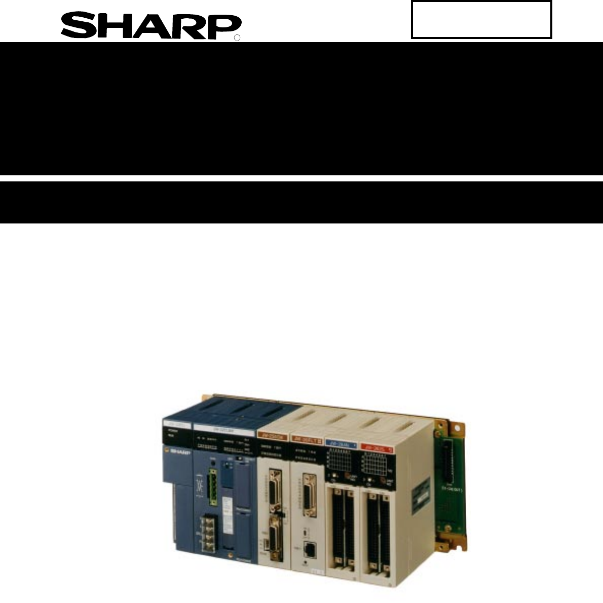
RSSharp Programmable Controller New Satellite JW30H Control moduleJW-32CUM1 Version 1.0Produced in Feb. 2003User's ManualModel name
1-1Outline1The JW-32CUM1 is a control module for the JW30H programmable controller. It has a built incommunication function. Its control section is co
DeviceNet (Master) Function8-378When an error occurs on a node (master and slave station), the error code and the node address will bedisplayed on the
DeviceNet (Master) Function8-388Display lampError detailsCommunicationoperationMasterstatus*TreatmentMS/NS/FTS7 to S0(errornode)MS: Keeps thecurrentst
DeviceNet (Master) Function8-398[2] Display of node addressesThe JW-32CUM1 displays node addresses using the S0 to S7 lamps on the display panel.Nodea
DeviceNet (Master) Function8-4088-6-2 Diagnostic tableThe diagnostic table that was specified in the JW-32CUM1 (control section) can be used to check
DeviceNet (Master) Function8-418Shown below are the addresses of the diagnostic table (communication monitor table, etc.) (1) Address of the communica
DeviceNet (Master) Function8-428 (3) Device status table addresses (master mode)When an error occurs on a slave station device, a device status code (
DeviceNet (Master) Function8-438Allocation system Fixed Free Node addressAddress39165*45339166 5439167 5539170 5639171 5739172 5839173 5939174 6039175
DeviceNet (Master) Function8-448 (4) Master status address (master mode)Displays error information and operation status by turning bits ON and OFF.*5:
DeviceNet (Master) Function8-458 (5) Vender information address (master mode)The vender information is used when SHARP provides services to JW-32CUM1
DeviceNet (Master) Function8-468[2] When JW-32CUM1 is used in the slave modeThe diagnostic tables contain a communications monitor table, an operating
2-1Precautions for Use2Chapter 2: Precautions for UseWhen using the JW-32CUM1 (JW-34KBM), pay attention to the following points (1) to (6) that descri
DeviceNet (Master) Function8-478Below shows addresses of the diagnostic table (communication monitor table, etc.)(1) Address of the communication moni
DeviceNet (Master) Function8-488 (4) Master status address (slave mode)Displays error information and operation status by turning bits ON and OFF.Allo
DeviceNet (Master) Function8-498 (5) Vender information address (slave mode)The vender information is used when SHARP provides services to JW-32CUM1 (
DeviceNet (Master) Function8-508* Output to slave station (when the control section is stopped) is determined by the value (00, 01(HEX))in system memo
Remote I/O (master station) function9-199-1 Remote I/O (master station) functionWhen the general purpose communication section in the JW-32CUM1 is use
Remote I/O (master station) function9-299-2 Setting methodWhen the remote I/O (master station) of the JW-32CUM1 is used, items that must be set for th
Remote I/O (master station) function9-39(1) Switch SW5Specify the communication function.- "1" when selecting remote I/O function.(2) Switch
Remote I/O (master station) function9-49[3] Data memory areaWhen using the remote I/O function (as a master station), the data memory in the JW-32CUM1
Remote I/O (master station) function9-594. When you want to install a special I/O module on a JW-21RS slave station, use a special I/Orelay as the dat
Remote I/O (master station) function9-69[4] I/O registrationWhen using the JW-21RS as a slave station, make sure to execute an "I/O registration&
2-2Precautions for Use2(12) Cautions for static electricitySignificant volume of static electricity may build up on the human body in extremely dry co
Remote I/O (master station) function9-79[5] Slave station settingsOn slave modules (such as the JW-21RS), specify a slave station number and the termi
Remote I/O (master station) function9-899-3 Required transfer time and its timing[1] Required transfer time Time necessary to communicate with all the
Remote I/O (master station) function9-99(2) 1 cycle operation of the PC(3) Timing in the case of 1 cycle time of the PC is longer than required transf
Remote I/O (master station) function9-109(4) Timing in the case of 1 cycle time of the PC is shorter than required transfer processingtime.When transf
Remote I/O (master station) function9-1199-4 Errors and treatment[1] IndicatorsLamps on the JW-32CUM1 (the CM-M section on the display panel) turn ON
Remote I/O (master station) function9-129[2] Operation in error conditionsThe communication status of the master and slave stations when run, stop, er
Remote I/O (master station) function9-139The operation condition of the JW30H (JW-32CUM1) and the slave module (when JW-21RS is used) inabnormal condi
Remote I/O (master station) function9-149[3] Error codeWhen an error occurs in remote I/O operation, the error code is stored in system memory locatio
Remote I/O (master station) function9-159 Errors on slave stationError codeContents Errors on master station40(H)42(H)44(H)46(H)47(H)48(H)60(H)70(H)71
Remote I/O (master station) function9-169(2) Store error history in the master stationWhen the error (error code 80(H) to 8D(H)) occurs in a master st
2-3Precautions for Use230HnWith "30Hn" mark30HWith "30Hn" mark Without any mark(18) Notes for using communication module, support
Remote I/O (master station) function9-179[4] Check flowWhen a communication operation on the remote I/O produces an error, check the following.(1) Whe
Remote I/O (master station) function9-189(2) FAULT lamp of the JW-32CUM1 lights OFFRespond according to the error code shown by the "ER, 1 to 80&
Remote I/O (master station) function9-199(3) Wiring checkCheck the wiring according to the following procedures, as error wiring may cause unstable op
10-1Data link DL1 (master station) function1010-1 Data link DL1 (master station) functionWhen the general purpose communication section in the JW-32CU
10-2Data link DL1 (master station) function10[1] Communication method of the data link DL1The data link DL1 communicates between a master station and
10-3Data link DL1 (master station) function10[2] Communication contents of data link DL1The data link DL1 function is available to communicate the dat
10-4Data link DL1 (master station) function1010-2 Setting methodWhen the JW-32CUM1 in used with data link DL1 (master station) function, items that mu
10-5Data link DL1 (master station) function10(1) Switch SW5Specify the communication function.- "2" when selecting data link DL1 function.(2
10-6Data link DL1 (master station) function10[3] Data memory areaThe data link area and communication monitor flags are allocated in the JW-32CUM1 (co
10-7Data link DL1 (master station) function10(2) Communication monitor flagThe communication operation of the data link DL1 can be monitored using com
2-4Precautions for Use2(19) Special I/O modulesIf a preset scanning time is too short ( less than 2 ms), the special I/O module such as JW-21SU maynot
10-8Data link DL1 (master station) function1010-3 Required transfer time and its timing[1] Required transfer timeNecessary time (T) to complete transf
10-9Data link DL1 (master station) function10[2] PC process and communication timingThe data link DL1 communicates asynchronize with master station PC
10-10Data link DL1 (master station) function10Remarks- The processing flow of a slave station is the same as those of a master station.- Data exchange
10-11Data link DL1 (master station) function10[3] Communicate delay timeThe following flow delay occurs when the JW-32CUM1 receives data as data link
10-12Data link DL1 (master station) function10[4] How to make synchronizeIn order to securely transfer data between a master station and a slave stati
10-13Data link DL1 (master station) function10[5] Hierarchy linkCreation of hierarchy link installing DL9 slave station and DL1 master station in a PC
10-14Data link DL1 (master station) function1010-4 Errors and treatment[1] IndicatorsLamps on the JW-32CUM1 (the CM-M section on the display panel) tu
10-15Data link DL1 (master station) function10[3] Error codeWhile in the data link DL1 process, when master station (JW-32CUM1) has an error, the JW-3
10-16Data link DL1 (master station) function10Store error historyWhen the error (error code 60(H)) occurs, stores error history in the JW-32CUM1 regis
10-17Data link DL1 (master station) function10[4] Check flowWhen a communication operation on the data link DL1 produces has an error, check the follo
3-1System Configuration3Chapter 3: System Configuration*1: Select any one of the four communication functions (master station) using the switches on t
10-18Data link DL1 (master station) function10(3) Wiring checkCheck the wiring according to the following procedures, as error wiring may cause unstab
11-1Data link DL9 (master station) function11Chapter 11: Data link DL9 (Master Station) Function11-1 Data link DL9 (master station) functionWhen the g
11-2Data link DL9 (master station) function11[1] Communication method of the data link DL9The data link DL9 controls to send data from a master statio
11-3Data link DL9 (master station) function11[2] Communication contents of data link DL9The JW-32CUM1 can transfer 2 to 128 bytes of data memory conte
11-4Data link DL9 (master station) function1111-2 Setting methodWhen the JW-32CUM1 in used with data link DL9 (master station) function, items that mu
11-5Data link DL9 (master station) function11(1) Switch SW5Specify the communication function.- "3" when selecting data link DL9 function.(2
11-6Data link DL9 (master station) function11[3] Data memory areaThe data link area and communication monitor flags are allocated in the JW-32CUM1 (co
11-7Data link DL9 (master station) function11(2) Data link DL9 operation flagThe data link DL9 link operation of the JW-32CUM1 (master station) is ava
11-8Data link DL9 (master station) function1133333 Individual monitoring flagThe individual monitoring flags are divided into 3 function flags: 1; Com
11-9Data link DL9 (master station) function11Remarks- "Invalid" means that each flag condition does not change.- Each flag condition of unco
3-2System Configuration3JW-34KBMJW-34ZB/36ZB/38ZBJW-31EA (Install in basic rack panel)JW-32EA (Install in all expansion rack panel)JW-05EC/1EC/3EC/10E
11-10Data link DL9 (master station) function1111-3 Required transfer time and its timing[1] Required transfer timeRequired time (T) for the data link
11-11Data link DL9 (master station) function11[2] PC process and communication timingThe data link DL9 communicates asynchronize with master station P
11-12Data link DL9 (master station) function11[3] Communicate delay timeThe following delay occurs when the JW-32CUM1 exchanges data as DL9 function.(
11-13Data link DL9 (master station) function11(2) Communication from slave station to slave station (from slave station to master station thento slave
11-14Data link DL9 (master station) function11[4] How to make synchronizeIn order to securely execute data transfer between a master station (JW-32CUM
11-15Data link DL9 (master station) function11[5] Hierarchy link(1) Hierarchy link combining DL1 and DL9Creation of hierarchy link installing DL9 slav
11-16Data link DL9 (master station) function1111-4 Errors and treatment[1] IndicatorsLamps on the JW-32CUM1 (the CM-M section on the display panel) tu
11-17Data link DL9 (master station) function11[3] Error codeWhen there is a switch setting error in the data link DL9 function, the JW-32CUM1 stores i
11-18Data link DL9 (master station) function11[4] Check flowWhen a communication operation on the data link DL9 produces an error, check the following
11-19Data link DL9 (master station) function11(3) Wiring checkCheck the wiring according to the following procedures, as error wiring may cause unstab
3-3System Configuration3(1) Control moduleemanledoM tuO/nIfo.oN ezismargorP retsigereliF,erutaefkcolCtropnoitacinummoc1MUC23-WJstniop4201sdrowK5.51set
12-1M-net (Master Station) Function1212-1 M-net (master station) functionM-net (interface between modules) is a communication system which makes data
12-2M-net (Master Station) Function12The followings are the Sharp PC modules that can be used as master stations and slave stations in the M-net syste
12-3M-net (Master Station) Function1212-2 SettingsWhen the JW-32CUM1 is used with the M-net function (master station), the items that must be set fort
12-4M-net (Master Station) Function1212-2-1 How to set (initialize) the M-net system— : Can be created : Cannot be createdSet the number of byte
12-5M-net (Master Station) Function1212-2-2 M-net data link areaThis section describes the setting details for data transmission and reception between
12-6M-net (Master Station) Function1212-2-3 Switch settingsSpecify the settings with switches SW5 (communication function), SW3 (mode), SW4 (transfers
12-7M-net (Master Station) Function1212-2-4 Parameter settingSet the number of bytes of data to be transmitted or received between the master and slav
12-8M-net (Master Station) Function1212-2-5 Communication programCreate an M net communication program and download it the master station PC (JW-32CUM
12-9M-net (Master Station) Function1212-2-6 Setting exampleThis section describes some setting examples when using JW-10CMs for slave stations 01 to 0
12-10M-net (Master Station) Function12[2] Setting procedure example[1] This section describes examples of the setting procedures for the system.Turn O
3-4System Configuration3(6) I/O, special I/O, option, I/O link, DeviceNet module*: Make sure to use the JW30H series applicable products for the JW-23
12-11M-net (Master Station) Function12Enter the master station (JW-32CUM1) programEnter the communication program to the master station PC.1 Enter the
12-12M-net (Master Station) Function12Enter the program for slave stations 01 to 07(8).Enter the program to enable communication with the slave statio
12-13M-net (Master Station) Function1212-3 Communication time and communication timing(1) Time required for transmissionThis section shows how to calc
12-14M-net (Master Station) Function1212-4 Errors and treatment12-4-1 IndicatorsThe lamps on the master station (JW-32CUM1) light according to the ope
12-15M-net (Master Station) Function1212-4-2 Error flag[1] Error flag detailsThe error flags are relays that are turned ON when the M-net is not able
12-16M-net (Master Station) Function1212-4-3 Error codeWhen an error occurs on the master station during M-net communications, the error code is store
12-17M-net (Master Station) Function12[2] Error code tableONOFFBitIndicator lampStatusBit LampLightsONGoesOFFError code (display)Details (See page 12-
12-18M-net (Master Station) Function12ONOFFBitIndicator lampStatusBit LampLightsONGoesOFFError code (display)Details (See page 12-16.)Hex-ade-cimalErr
12-19M-net (Master Station) Function12[3] Storing an error code in the system memoryWhen an M-net communication error occurs in the master station PC
13-1Specifications1313-1 JW30H (JW-32CUM1) general specificationsShown below are the general specifications when using the JW-32CUM1 as a control modu
3-5System Configuration3(7) Support toolsemanledoM eniltuO skrameRGP41-WJyalpsidxirtamtodDCL-----------GP31-WJrofegaptxenehtnielbatehteeSsnoisrevGP21-
13-2Specifications1313-2 JW30H (JW-32CUM1) system specificationsShown below are the system specifications when using the JW-32CUM1 as a control module
13-3Specifications13Data memory13-3 JW-32CUM1 performance specifications and communication specificationsShown below are the performance specification
13-4Specifications13Items SpecificationsData memoryTimer/counter/MDRegisterCurrent timerstorage registerTotal 1024 points (000 to 1777 : common for bo
13-5Specifications13File 1 (16K bytes)File 2 (Switchover between 32 K and 64 K bytes)Total 48K/80K bytesItems SpecificationsData memoryThis register c
13-6Specifications13ItemsSpecificationsSystemmemoryNumber(OCT)Contents#010 to 017 Monitor the timer.#030 Monitor the minimum scanning time. (lower dig
13-7Specifications13Items SpecificationsParameter memoryParameter for special I/O module : 128 bytes x 32 modulesParameter for special I/O module (Ins
13-8Specifications13[2] Communication specificationsShown below are the specifications for the communication port, DeviceNet communication port, andge
13-9Specifications1313-4 JW-34KBMShown below are the specifications for the JW-34KBM basic rack panel.Item SpecificationNumber of slotsSlots for a pow
Thank you for purchasing our JW-32CUM1 control module for the JW30H series programmable controller.This manual describes the system configuration of t
3-6System Configuration3Description of software version approved to JW30H (JW-32CUM1)The following support tools may, or may not be compatible with JW
3-7System Configuration3(9) PG connection cableModel nameJW-22KCJW-24KCConnection cable between a support tool and the JW30H. 2 mConnection cable be
4-1Name and Function of each part4Chapter 4: Name and Function of Each Part4-1 JW-32CUM1 (Control module)[1] Front view, side viewPG/COMM1PG/COMM2JW-3
4-2Name and Function of each part4[2] Rear view12345612345678CBA9876543210FEDCBA9876543210FEDCBA9876543210FEDCBA9876543210FEDCBA9876543210FED12345678C
4-3Name and Function of each part44-2 JW-34KBM (Basic rack panel)The JW-34KBM shall be used as a basic rack panel when the JW-32CUM1 is used as a cont
5-1Installation5[1] Installation of the JW-34KBMDrill M5 tapped installation holes on the control panel wall and secure the JW-34KBM basic rack panel
Connection (Wiring) Method6-166-1 Connection to a DeviceNet communication connector[1] Preparing a communication cableBelow describes how to install a
Connection (Wiring) Method6-26Miniature flat blade screwdriverCable securing screwGroundBlue (CAN L)White (CAN H)Black (V —)Red (V+)Connector (mountin
Connection (Wiring) Method6-36[2] Connecting a communication cableMatch the orientation of the connector on the communication cable (DeviceNet) with t
Connection (Wiring) Method6-466-2 Wiring to the general-purpose communication terminal blockConnect the communication cable for general-purpose commun
Read this manual and attached documents carefully before installation, operation, maintenance and checkingin order to use the machine correctly. Under
Connection (Wiring) Method6-566-3 Wiring to the communication port[1] Communication port pin arrangement of PG/COMM1 port, PG/COMM2 portPG/COMM1 port*
Connection (Wiring) Method6-66[2] Wiring figure(1) When using RS-232C for communication method of host computer side.Be within 15m for the total lengt
Connection (Wiring) Method6-766-4 Wiring JW-34KBMWire the 5V and (FG) terminals and the I/O expansion connector on the JW-34KBM basic rack panel.- Be
Directions for use7-177-1 Current consumption of moduleEach module in the JW30H (JW-32CUM1) operates by 5 VDC output current supplied by the powersupp
Directions for use7-2744444 I/O, special I/O, option, I/O link, and DeviceNet moduleModel nameCurrentconsumption : mA(when all points ON)No. of curren
Directions for use7-37(2) Calculation of current consumption (by current consumption mark).Add up the total numbers of the current consumption mark on
Directions for use7-477-2 Allocation of the relay numberRelay numbers of input, output, special, and option module are assigned by automatic registrat
Directions for use7-57(2) Table creationIn the expansion rack panel (rack numbers 1 to 7), the top address of relay number is set in evenaddress (with
Directions for use7-67[2] I/O relays allocated to each moduleRelay numbers in each rack panel are automatically allocated in series following each rac
Directions for use7-77 Module installation exampleslortnoCeludomledomemandellatsniseludomforebmunmumixaMforebmuNO/IlortnocstniopO/IforebmuNnoitacollay
(4) Maintenance Danger- Never connect battery in wrong polarity, or charge, disassemble, heat, throw into fire, orshort-circuit. Or it may be broken o
Directions for use7-87[5] Allocation example of relay number(1) Example of auto registrationThis is to show the relay numbers in the following system
Directions for use7-97Module name Model nameModuleNo.switchByte address Flag areaNo. ofinstallation64 points input JW-264NRefer to the next pageMax. 2
Directions for use7-107Rack 301234567コ3600 to コ3617コ3620 to コ3637コ3640 to コ3657コ3660 to コ3677コ3700 to コ3717コ3720 to コ3737コ3740 to コ3757コ3760 to コ3777T
Directions for use7-117(2) In case of basic system plus remote I/O systemUp to 8 sets are set in the remote I/O slave station by module No. switch.012
Directions for use7-1277-4 Communication portThe JW-32CUM1 control module has communication ports (PG/COMM1, PG/COMM2).The communication port can comm
Directions for use7-137[1] Set system memory of JW-32CUM1Set system memory #234/#235 (communication port 1) and #236/#237 (communication port 2) forco
Directions for use7-147Turn ON powerCOMM port (#234, #236)PG port (19,200 bits/sec.)PG port (115,200 bits/sec.)PG port (9,600 bits/sec.)Remarks- Chang
Directions for use7-157As for the detail of each command, see "List of commands" on pages 7-19, and "Computer link" section ofuser
Directions for use7-167Contents of communication format*: (H) indicates upper digit, (L) indicates lower digit.Contents of error codeASCII code3A HEX3
Directions for use7-177Command contentSumcheck area?(H) (L)(H) (L)CRADADSCSCSumcheck code SC (H), SC (L)The communication port detects error using sum
Chapter 1: OutlineChapter 2: Precautions for UseChapter 3: System ConfigurationChapter 4: Name and Function of Each PartChapter 5: InstallationChapter
Directions for use7-187Response time RIWhen a personal computer is interpreter system, it executes programs one by one while interpreting.This persona
Directions for use7-197Each command can be executed in the write mode or when the JW30H (JW-32CUM1) is in thefollowing state.O: Executable x: Non-exe
Directions for use7-207(3) Address expression systemIn each command, the setting value in the following table is set in the address module ofcommunica
Directions for use7-2177-5 Exchange method of batteriesExchange battery for memory back-up in JW-32CUM1 control module within its validity.Battery mod
Directions for use7-2277-6 Self-diagnosis functionBy the self-diagnostic function, the system is running while checking if its own hardware is normal
Directions for use7-237[2] Self-diagnosis function (Error code table)Item ContentsPCoperatingconditionHaltoutputJW-32C-UM1Indication lamp ofpowersupp
Directions for use7-247*3 The special relay: 7370 to 7377 are special relay which are turned ON when detected in self-diagnosis.In the event of abnorm
Directions for use7-257 Check flow1 Check flow2 Check flow3 Check flow4 Check flow5 Check flow1ONOFFOFFOFFONFault(Control module)OFFOFFBlinkO
Directions for use7-267[4] Check flow(1) Check flow 1Monitor system memory #160 using a hand-held programmer.Contents of#160 (HEX)32, 3523, 24, 262544
Directions for use7-277(2) Check flow 2(3) Check flow 3Is operation of JW-32CUM1 normal?Check power voltage of power terminal of the JW-32CUM1.LED err
Table of contentsChapter 1: Outline ... 1-1[1] Devi
Directions for use7-287(4) Check flow 4This flow shows the checking procedure in the event of abnormality of input signal not detected by theself-diag
Directions for use7-297(5) Check flow 5This flow shows the checking procedure in the event of abnormality of output signal not detected bythe self-dia
Directions for use7-3077-8 Support tool[1] Kinds of support toolThe support tool that can be used in the JW30H (JW-32CUM1) are classified into models
Directions for use7-317[2] Directions of use JW30H non-applicable support toolThis section explains the manner of manipulating the JW30H by using the
DeviceNet (Master) Function8-188-1 DeviceNetThe JW-32CUM1 can be used to communicate as a master or slave module in a DeviceNet. Connection exampleCha
DeviceNet (Master) Function8-28[1] Network names and functionsThis section lists the device names and functions used in DeviceNet networks. A example
DeviceNet (Master) Function8-38[2] Connection methodThere are two methods for connecting nodes: T branch and Multi-drop.(1) T branch methodYou can mak
DeviceNet (Master) Function8-48[3] Cable length(1) Maximum network lengthThe maximum network length will be the longest of the following:1. The distan
DeviceNet (Master) Function8-58[4] Power supplyConnect the communication power supply to the trunk.Two of the five conductors in the cable used for tr
DeviceNet (Master) Function8-68[5] Communication related devicesIn addition to master and slave nodes, the following devices can be used in this syste
[4] Check flow ... 7-267-8 S
DeviceNet (Master) Function8-78(6) Communication power supplyMake sure to use a power supply device for communication that conform to the specificatio
DeviceNet (Master) Function8-888-2 Setting methodWhen the JW-32CUM1 is used with the DeviceNet function, items that must be set for the DeviceNet area
DeviceNet (Master) Function8-98[2] Switch settings (operation)Set SW7 and SW8 and operate the SCAN switch on the JW-32CUM1.(1) Switch SW7Select a basi
DeviceNet (Master) Function8-108(O: Valid setting —: Invalid setting)Note: Do not set switch SW8 to "3, 7, B, or F." Otherwise, a malfunct
DeviceNet (Master) Function8-11833333 Communication monitor timeThe communication monitor time (ISD, EPR) refers to the time out time for communicatio
DeviceNet (Master) Function8-128Remarks- When setting an option module (such as the JW-22CM) is installed on the JW-34KBM basic rackpanel (and the JW-
DeviceNet (Master) Function8-138The settings in system memory related to DeviceNet communication in the JW-32CUM1 are describedbelow.(1) Top address o
DeviceNet (Master) Function8-148(4) Top address in the scan list table (when master mode and free allocation are selected)This is a system memory loca
DeviceNet (Master) Function8-158(6) Communication monitor time (ISD, EPR) Initial value of ISD, EPR (when set to 0)- The initial values of ISD and EPR
DeviceNet (Master) Function8-168(8) Top address of the I/O table (when in the slave mode)This system memory location is used to store the top address
9-4 Errors and treatment ...9-11[1] In
DeviceNet (Master) Function8-178[4] Table of switches, data memory, and system memory settings(1) When the JW-32CUM1 is used in the master modeSwitch
DeviceNet (Master) Function8-188System memory settings (master mode)*1: When this value is 00(HEX), "fixed allocation" will be enabled.When
DeviceNet (Master) Function8-198(2) When the JW-32CUM1 is used in the slave mode Switch settings (slave mode)Switch name Setting detailsSetvalue---Di
DeviceNet (Master) Function8-208 System memory settings (slave mode)Set detailsSetvalueItem Set range#300 to#303Not used --- Fix to 00(HEX)00#304#305
DeviceNet (Master) Function8-2188-3 I/O message functionAmong I/O messages of the DeviceNet, the JW-32CUM1 (DeviceNet) supports Polling I/O function a
DeviceNet (Master) Function8-228Address *1st byte (コ2000)2nd byte (コ2001)3rd byte (コ2002)4th byte (コ2003)5th byte (コ2004)6th byte (コ2005)7th byte (コ
DeviceNet (Master) Function8-238Address * Value (hexadecimal): Details1st byte (E0000) FF: This JW-32CUM1 station (master)Nodeaddress 02nd byte (E0001
DeviceNet (Master) Function8-248(2) Even number allocationAssign the number of bytes of data in the input/output data table (data length) in the order
DeviceNet (Master) Function8-258The scan list data table (- 8-29) for this example will be as follows:Address * 1 Value (hexadecimal): Details1st byte
DeviceNet (Master) Function8-268(3) Allocation in the order in which vacant nodes are occupiedAssign the data length (number of bytes of data) in the
Chapter 12: M-net (Master Station) Function ...12-1 to 12-1912-1 M-net (master station) function ...
DeviceNet (Master) Function8-278The scan list data table (- 8-29) for this example will be as follows:Address * 1 Value (hexadecimal): Details1st byte
DeviceNet (Master) Function8-2888-3-2 Editing the scan listBefore using the DevceNet function of the JW-32CUM1 for the first time, you will have to e
DeviceNet (Master) Function8-298[2] Scan list tableThe scan list table (512 bytes) addresses and details are shown below. Addresses in the scan list t
DeviceNet (Master) Function8-3088-4 Explicit message functionWhen using only the I/O message function, there is no need to use the "explicit"
DeviceNet (Master) Function8-318(2) Details of the Explicit message table (responses)Control section reading flag, DeviceNet section writing flag etc.
DeviceNet (Master) Function8-328(3) Parameter addresses for the Explicit message table (requests, responses)Shown below are the parameter addresses.Al
DeviceNet (Master) Function8-338(4) ExampleShown below is an example of reading the vendor ID of the identified object in a slave station (nodeaddress
DeviceNet (Master) Function8-3488-5 Communication timingThis chapter describes DeviceNet section the communication between the JW-32CUM1 (control sect
DeviceNet (Master) Function8-358[2] When the I/O message communication time is longer than the JW-32CUM1(control section) cycle operation time(1) Comm
DeviceNet (Master) Function8-3688-6 Error handlingWhen an error occurs during communication with the JW-32CUM1 DeviceNet communication, check theerror
Další dokumenty pro Multifunkční zařízení Sharp JW-20FLT

Související produkty a manuály pro Multifunkční zařízení Sharp JW-20FLT
 (148 stránky)
 (160 stránky)
(12 stránky)
(160 stránky)
(12 stránky)

 (165 stránky)
(201 stránky)
(178 stránky)
(116 stránky)
(116 stránky)
(165 stránky)
(201 stránky)
(178 stránky)
(116 stránky)
(116 stránky)
© 2020, manymanuals.cz. Všechna práva vyhrazena. | 0.028 s |
 Manymanuals.com
 Manymanuals.de
 Manymanuals.fr
 Manymanuals.it
 Manymanuals.pl
 Manymanuals.cz
 Manymanuals.es
 Manymanuals-pt.com
Komentáře k této Příručce